← All projects
PROJECT / 03SOFT ROBOTICS / MATERIALS / TESTING

Soft Robotic Finger

Developed a TPU-and-silicone robotic finger with adjustable stiffness, flex sensing, pressure-displacement testing, and finite element analysis.

Soft RoboticsMechanical DesignTPUSiliconeFEASensorsTesting
HERO / 01FEA Displacement
01 / OVERVIEW

A compliant actuator with mechanically adjustable stiffness.

Three pneumatic pistons reposition stiff blocks inside the compliant finger; physical pressure-displacement tests and measured material data provide direct checks for the finite element model.

02 / FINITE ELEMENT ANALYSIS

Pressure loading and nonlinear material behavior.
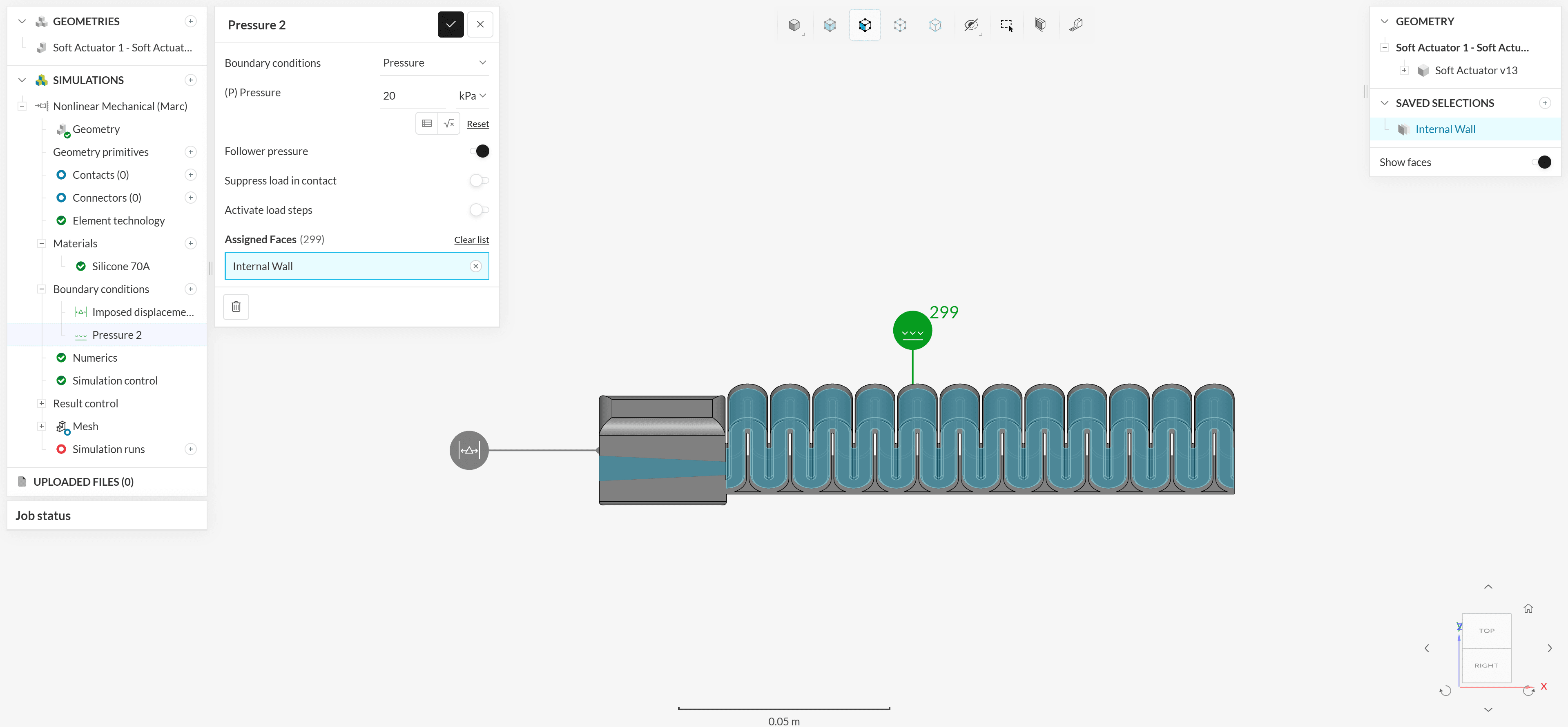
Finite element model of the soft robotic finger with a 20 kilopascal pressure boundary condition applied to its internal walls
02 / 01Internal Pressure Boundary Condition
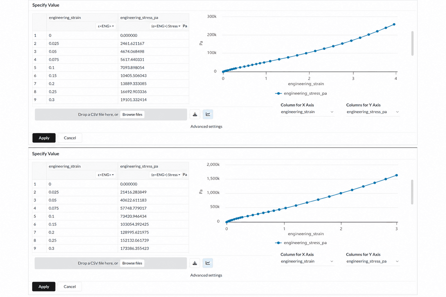
Two compact engineering stress-strain tables displayed beside their corresponding material curves
02 / 02Material Stress-Strain Data

The simulation applies a 20 kPa follower pressure to the actuator's internal walls and uses measured stress-strain inputs to represent the nonlinear response of the soft materials.

03 / ADDITIVE MANUFACTURING

A variable-stiffness finger built into one compliant structure.
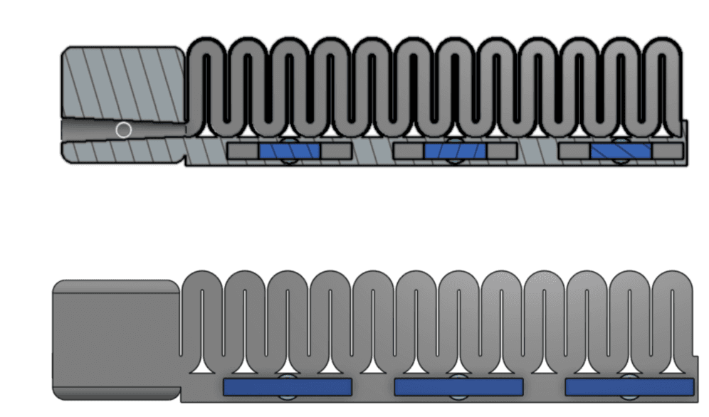
Section and exterior CAD views showing three stiff blocks actuated by pneumatic pistons along the soft robotic finger
03 / 01Variable-Stiffness Mechanism
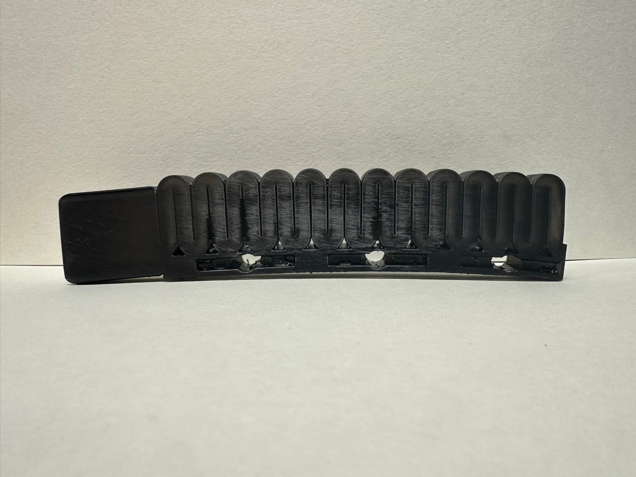
Black additively manufactured variable-stiffness soft robotic finger shown straight against a neutral background
03 / 02Printed Soft Robotic Finger

Three pneumatic pistons move stiff blocks in and out of the compliant finger, varying its bending stiffness.

04 / SETUP + TESTING

Simulation checked against controlled physical testing.
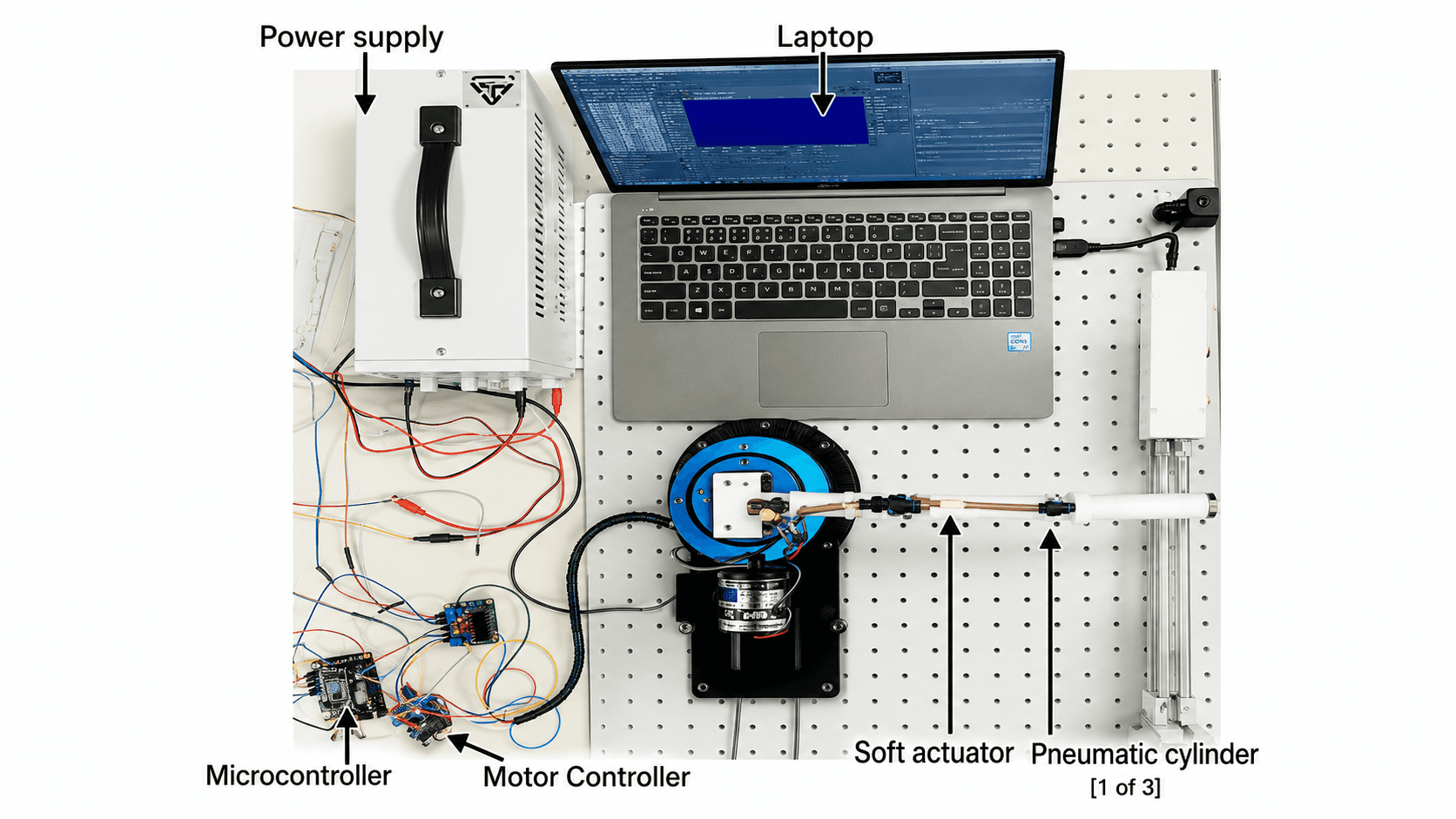
Labeled soft actuator test setup with power supply, laptop, microcontroller, motor controller, and pneumatic cylinder
04 / 01Experimental Test Setup
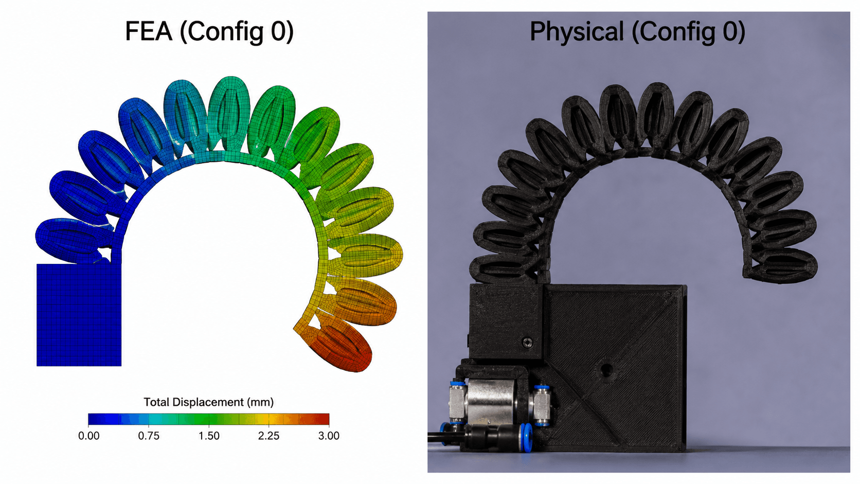
Side-by-side comparison of finite element displacement prediction and physical soft robotic finger deformation
04 / 02FEA + Physical Comparison

The instrumented test setup coordinates pneumatic input, actuator displacement, motor control, and data capture; the resulting physical deformation is compared directly with the FEA prediction.